Kleindiek FMS force measurement system
MS-EM is a compact force readout tool to perform force measurement and nano-indentation experiments in combination with a Kleindiek MM3A-EM and MM3E micromanipulator.
Applications:
- Nanoindentation
- Tensile measurement
- Stretching of CNTs
- MEMS analysis
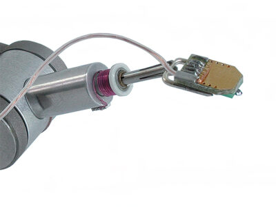
The measurement of the smallest outer dimensions are possible by means of a force readout system that requires no laser. The FMS sensor can conveniently be placed at the point of interest and in combination with a optional rotational tip can be set to a particular angle of ‘attack’. Force feedback on the display of the controller is coupled with a loudspeaker to enable you to intuitively characterize materials and micromechanical structures by their resonance frequencies. Sharp silicon tips allow nano-indentation in a wide variety of materials.
The force measurement system offers a complete solution including software for data acquisition, visualisation and export. The controller offers easy operation, measurement calibration at the touch of a button and a USB interface. The novel software features a calibration wizard for the force measurement tips and is capable of recording force-time curves.
It is recommended that you calibrate the FMS before each experiment to ensure accurate measurements. This can be carried out quickly and easily in your SEM using the FMS software and the calibration spring provided. Each calibration spring has its own unique spring constant, which is engraved into its housing. The wizard built in to the FMS software enables you to enter the spring constant and then guides you through the process of calibration. The FMS software remembers the voltage difference recorded during calibration and uses this together with the spring constant to calculate the force for subsequent experiments. Force is displayed through the FMS software.
Operation:
Kleindiek FMS is a plug-in tool for the MM3A-EM micromanipulator comprising a cantilever, a resistor bridge, an amplifier, an analogue output, a loudspeaker and a display. The resistor bridge is integrated into the cantilever (FMT) and the other components are integrated into the FMS controller. The FMT is covered with piezo-resistive material. When it is brought into contact with a sample (and is thus bent), this material generates an electrical signal. The material is one of the components of the resistor bridge, so that the resistance of the bridge changes when the cantilever is bent. By applying a voltage to the bridge, the change in resistance can be converted into a change in voltage.
The voltage changes at the resistor bridge are amplified and the amplified signal is output by the FMS controller in three different ways:
- through the BNC plug on the rear of the FMS controller (maximum output voltage range is ± 12 V)
- on the display on the front of the FMS controller
- through the loudspeaker in the FMS controller
- via USB using the FMS software provided

PL-FMS-EM-000 Force measurement system
A force sensor plug-in tool for the MM3A-EM and MM3E. The system consists of a force sensor holder, control module with preamplifier and a loudspeaker, PC software, a power supply, ten force sensors and an operator’s handbook.
Tip force constant (calculation): 30 to 40 N/m
Maximum tip force: 360 μN¹
Resistance: 500 to 650 Ω
Sensitivity: 18.8 x 10⁻³ mV/nm at Vbridge = 2.5 V²
¹ Calculated with assumptive deflection of 10% and the lowest force constant.
² Dependent on the bias voltage (Vbridge) that is applied to the series resistance of sensor and reference.
All technical specifications are approximate. Due to continuous development, we reserve the right to change specifications without notice.
Technical specifications FMT-120 sensors
Length 120 μm
Width 50 μm
Height 4 to 5 μm
Tip radius < 20 nm
Tip height > 5 μm
Tip force constant (calculation) 30 to 40 N/m
Force resolution 10 nN
Maximum tip force 360 μN
Resistance 500 to 650 Ω
Sensitivity 18.8 × 10⁻³ mV/nm at Vbridge = 2.5 V 2
Lowest pressure 10-7 mbar
1 Calculated with assumptive deflection of 10% and the lowest force constant
2 Dependent on the bias voltage (Vbridge ) that is applied to the series resistance of
sensor and reference
Ordering information:
Kleindiek FMS force measurement system
A working force measurement system consists of the FMS, MM3A-EM micromanipulator and a suitable mounting bracket for your SEM /FIB.